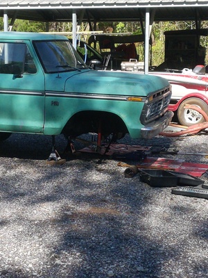
Here we go again! Due to my ignorance, I had to tear out my 1973 F100’s front-end yet again to replace the kingpins, because the passenger’s side was seized up and causing problems steering. After doing this project twice now, I thought I would provide a guide on how to do the whole front-end with pictures and detailed descriptions for those in need. This is not the easiest job on the truck, so steel yourself with great patience, and do not expect to be done in just an afternoon.
There are bound to be mistakes in this guide, so by all means send me corrections via email, but since the job is still fresh in my mind, I know I am very close.
I will speak only of my 1973 F100 2WD, but these instructions should be applicable to most if not all Fords using the Twin I Beam suspension. I will describe a full-teardown, and for ease, I recommend it over struggling underneath the truck.
Disassembly
Get the Tires Off
Before jacking the truck, break loose the lugs with a 13/16ths lug wrench without totally removing them. Then jack the truck on the frame somewhere behind the radius arms, leaving enough room for you to access the radius arm bushings later. You’ll probably need to use a chunk of 4x4 to lift it high enough, then place jackstands. Finish removing the tires, jack the suspension if necessary, and set them aside.
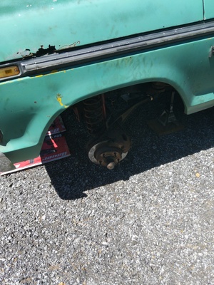
The Brakes
To remove the disc calipers, first compress the pad to the hub using a C-clamp or other tool. Then, using a 9/16ths, remove the bolt securing the sliding “key” from the spindle. Then remove the sliding “key” and spring (the bent piece of metal) using a hammer and chisel (this contraption pushes the caliper against the spindle so it doesn’t move nor rattle). The parts will likely go flying so be sure to reclaim them for later. Now the caliper should be free: set it aside where it won’t get damaged nor damage the brakeline.
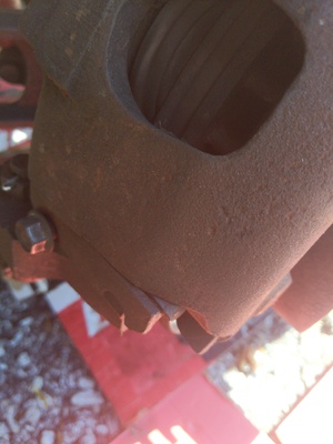
Very Important! Do NOT lose your anti-rattle clips from the assembly! Take them off and put them somewhere safe! If you lose them, you’ll find out just how annoying brake chatter can be!
Wheel Bearings and Hubs
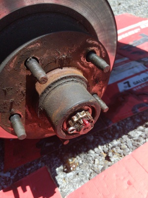
This is a great opportunity to replace your wheel bearings, because you will need to remove them for this job. Using a hammer and chisel, remove the dust cap from the center of the hub. Inside, you’ll see a strange, castellated retainer with a cotter pin. Remove the cotter pin, the retainer, and the 1 1/8th nut (or 1 1/16th, I cannot remember). Be careful, as the hub can slip off the spindle at this point; don’t let it hit you. Remove the bearing on the outside with its washer and set aside if reusing, or junk’em if replacing. Take the hub off and set aside. With all that done, go ahead and remove the dust cover behind the hub using a 1/2 socket on 3 stubby bolts. Set aside. There should be nothing left but the spindle now.
Tie Rods/Drag Link
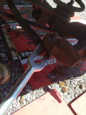
Now to remove the connections from the steering system to the spindles. It may be easier for you to disconnect from the Pitman Arm underneath the truck first before disconnecting from the spindles. It is up to you. Remove the cotter pin, then remove the castellated nut using a 7/8ths wrench or socket. Then, shove a pickle fork between the rubber boot and the spindle, hammer it in deep, then pry until the threaded section comes out of the spindle. May take some fennagling. Once the spindle is free from everything but the I-beam, you are ready to move on. I just left the whole drag link and tie rod assembly laying there.
Coil Springs
Using a 9/16ths socket, remove one of the bolts securing the metal strap to the top of the coil spring, and loosen the other just enough to free the top of the coil spring. Now, with 1 1/8th wrench or socket wrench with a bunch of extensions, remove the nut down the center of the coil spring. Remove the odd washer that retains the bottom of the coil spring and set aside. Now, the coil spring can be removed, though you may need the pickle fork or crowbar to assist in removing. You could also remove the bottom of the shock to help, but it is not strictly necessary.
With that out of the way, there is another very oddly shaped washer to remove, and a 1 1/8th nut. Hold off on removing that nut until we deal with the I-beams.
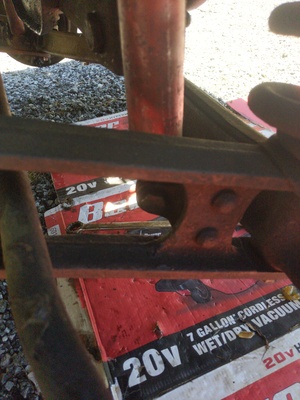
The I-Beams
Here is the most aggravating part of the project, so be patient. Go underneath the truck and look for this (mine is already partially knocked out):
The bolt is 1 1/8th and its nut is 15/16th. Remove the nut, and you’ll probably need to hammer the bolt out, but be careful not to damage it; set all hardware aside. If the I-beam still won’t descend, crowbar it down. Now go back to where the coil spring was and remove that 1 1/8th nut and the very long bolt that runs from the bottom of the radius arm through the I-beam. Be careful not to drop the I-beam on yourself. You should be able to pull the whole I-beam out and take it somewhere comfortable to work. Just you wait until you have to reinstall…
What a sad sight!
Axle Pivot Bushings
This is a great opportunity to replace your axle pivot bushings; they are the bushings opposite the spindle side of the I-beam, where you drove out the 1 1/8th inch bolt with the 15/16ths nut. A machine shop can probably do it for you, but you can DIY it if you want. Here’s how I would recommend doing it.
Rent or purchase a ball joint press. Have a hammer, chisel, and maybe a sawzall at the ready. Get the old bushing out by removing the rubber part, and cutting the metal sleeve up with the sawzall, being careful not to damage the I-beam. Use the hammer and chisel to remove the the sleeve. I had to bevel my new bushings on a sander to get them to fit, but you may not need to. With the new bushings, press them in with the ball joint press. You’ll probably need an impact driver to run the press with any degree of efficiency.
Easy done it. This is guaranteed to improve the truck’s handling of potholes and other road irregularities.
Radius Arm Bushings
This is pretty self-explanatory. With the I-beams out of the way, you just need to remove the cotter pin and 1 1/8th nut from the rear of the radius arm in order to replace the bushing. Take note of how the old one was oriented. Again, easy done it with the I-beams removed.
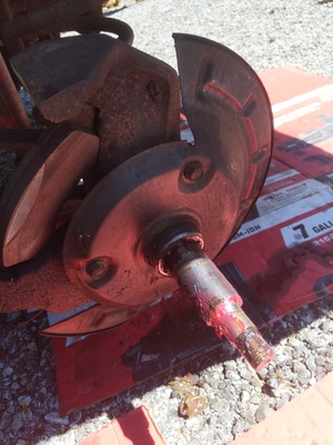
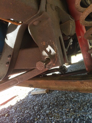
The Kingpins
The kingpin is what joins together the spindle and the I-beam. You should see a grease fitting on the top and bottom of where it is located. Remove the grease caps using a 7/8ths wrench. The round stock underneath those caps is the kingpin. Now, using an 11/16ths, remove the nut and lock washer on the side of the I-beam. These secure a locking lug that keeps the kingpin from moving too much. Using a hammer and punch/drift, drive the old lug out. Notice its odd shape and orientation for future reference.
Now to drive out the kingpin. If you are lucky, all you need is a large punch and a hammer to send the kingpin out, but chances are good it is seized up like mine. My driver’s side came out with no trouble, but the passenger’s was an ordeal. If it won’t come out within 20 or so raps, give up and try either heat or a press. I called a retired mechanic friend to get his advice: he said come on over and we’ll get it out.
First, we made a large punch out of the kinpin that came out. Then, using an oxyacetelyne torch (don’t bother with propane), we heated the I-beam where the kingpin passes through. Once it was hot, we placed the makeshift punch on the bad kingpin, and sledge hammered it until the bad kingpin came out. If you don’t have access to such a friend with goodies like a oxyacetelyne torch, find a good machine shop that can do the same thing, or have it pressed out. You’re going to need a machine shop for the next step anyway.
New Parts
The Machine Shop
With your kinpins removed and new kingpin kit in hand, take your spindles to the machine shop. The machinist will need to ream your new metal bushings from the kit to fit them to your spindles. He’ll then press them into place. Once your spindles are squared away, take them back home and get the new kingpins in.
Installing the New Kingpins
This may seem a little confusing, so be careful and take your time to understand before wailing away with the hammer. Read ALL of this before actually doing it. My kit was MOOG kit, so I’ll describe it, though other kits should be the same or very similar. Mine had parts I did not need that are apparently applicable to later Fords but not mine so be aware of that. We need to rejoin the I-beam and the spindle: the I-beam’s swoop should be UP not down. Now, place as much shim stock as you can on the bottom of the spindle where the I-beam will join it. I used two shims for each side. Then put the bearing on top of the shims with the movable part facing up so that the I-beam can move on it. Now, insert the I-beam (again, swooping up), and line everything up as best you can by looking down the spindle’s top hole.
Notice how your kinpin has a notch? That notch is how the weird lug from earlier secured it to the I-beam. As you insert the kinpin, you want to have that notch lining up with the hole in the I-beam so that the locking lug can secure it. Line up the kingpin, and drive it in with a hammer, being careful to not smash it particularly hard, else you risk flaring it out. If you have everything lined-up nicely, it’ll drive in just fine; you may need a socket to use as a punch to get the kingpin all the way in. Now, turn your attention toward the hole in the I-beam.
You should see your kingpin’s notch through that hole. If you don’t, rotate the spindle until you do, or drive the kingpin back out and try again. This must be perfect. Once lined-up, get that weird locking lug that is threaded, orient it so that the tapered side faces the kingpin, and drive it in with a hammer. It should go in without too much force; if you really have to wail on it, check your alignment and try again. Once it is in successfully, confirm everything is working by rotating the spindle and watching that the kingpin is not rotating too much; the lug prevents a full rotation.
Finish up the job. Put a lock washer and 11/16th nut on the locking lug to secure it to the I-beam. Place a small rubber seal on the bottom of the kingpin if your kit has one. Put new grease caps on the top and bottom of the spindle with a 7/8ths wrench and put new grease fittings on the caps using an adjustable wrench. Grease it up with a grease gun to be certain everything is in working order. The spindle should rotate very easily once greased, making your steering much easier when reassembled.
Reassembly
I-Beams
Now for some real aggravation; get at least one friend to help reinstall the I-beam. First, put the I-beam into the radius arm and put the 7 1/2 inch bolt up through them both. Secure them with a 1 1/8th nut, but NOT tightly; you need some play in the I-beam to get it secured back onto the frame. You’ll need to do a lot of fennagling with the floor jack on the spindle, the crowbar, and the pickle fork to get the I-beam to line up with where it is supposed to connect to the frame. This is easily the most aggravating part of the job. Best thing I can suggest is to get one side of the bushing’s eye lined up, drive the 1 1/8th bolt through it part-way, then use the floor jack on the spindle to manipulate the orientation of the eye. Once lined up, drive that crap in with a hammer and secure it with the 15/16ths nut before it changes its mind. Repeat for the other side. You can tighten up the nut and bolt that connects the I-beam and radius arm now.
Coil Springs
First, put the weird washer with the hump in it correctly onto the I-beam and radius arm junction. Put the coil spring over the bolt, and jam it underneath where it connects with the little metal strap. Put the other weird washer on facing upwards like a bowl on the bolt coming from below. Secure it down with 1 1/8th wrench, and place the metal strap on the top of the coil spring and tighten it down with the 9/16ths bolts. It may help to disconnect the shock.
Drag Link and Tie Rods
Reconnect the drag link and tie rods in whatever order you like, but it helps to not have to fight against the Pitman Arm. Replace all the 7/8ths castellated nuts and put fresh cotter pins through them. If you want to replace the tie rod boots with a kit from LMC, now is a good time. DO NOT FRICK WITH THE ADJUSTMENT SLEEVE BETWEEN THE INNER AND OUTER TIE ROD! This component affects the alignment of the vehicle so don’t touch it now, nor touch it at all unless you know what you are doing.
Wheel Bearings and Hubs
Replace the dust shield using the 3 1/2th bolts. Then, using high temperature wheel bearing grease, pack the spindle with grease, then place the hub on the spindle. Grease pack the bearings as necessary, or replace the bearings and pack them heavily with grease. Once everything is well packed, put the washer with the flat spot in the middle on the spindle, and secure it with the 1 1/8th nut (or 1 1/16th, I don’t remember). Put the castle retainer over the spindle, then install a fresh cotter pin. Hammer the dust cover over the whole thing.
Brakes
Replace your anti-rattle clip and the inner brake pad. Put the outer brake pad into the caliper and put the caliper into position on the hub. It should be loose. Using a hammer and chisel, drive the brake “key” with the spring on top of it between the caliper and spindle to tighten things up. Don’t forget to secure the “key” with a 9/16ths bolt.
NOTE: Because we compressed the brakes earlier, when you first go to drive again, they won’t hardly work. Build up pressure by just mashing the brake pedal in the driveway until the pedal offers up some resistance. You’ll be good to go after that. Double check your brake fluid while you’re at it, and top off with DOT 3 if needed.
Tires
Easy done it. You may need to floor jack the spindles to raise the hub high enough to accept the tire. Get the tire on there, and get the lug nuts hand-tight. Repeat on other side. Once done, lower the truck onto the ground and tighten the 13/16ths lug nuts with a lug wrench or whatever you prefer as long as they’re tight.
All Done
Quite a job ain’t it? If you can accomplish all this, you’ll become a Twin I Beam expert, and your front-end will suck much less. The steering will be much more responsive and potholes will no longer send the vehicle reeling into the nearest gully. But before you consider the job, make sure you know a good machine shop that can ream your kingpin bushings, and have a way of removing a seized kingpin.
A mechanic’s shop will probably charge a fortune for all this work, but the components are not all that expensive; I therefore recommend you supply your own labor. I estimate it cost me this much: ~$120 for the kingpin kit, ~$40 for radius arm bushings, ~$24 for both axle pivot bushings, and $80 for machine shop labor; this totals to $264.
If you decide to do this job, feel free to email me for help, or even meet in person if you’re in South Carolina.